When you install System Console, a default cluster named DefaultCluster is created automatically. The configuration of the default cluster differs depending on which of the following scenarios you have:
You installed System Console individually, either on the same machine as BIRT iHub, or on a different machine. If you installed System Console individually, you must log in to System Console and add the machine on which you installed BIRT iHub as a node to the default cluster. For information about adding the first node to this cluster, see How to add the first cluster node to a cluster.
You installed System Console and BIRT iHub using the install procedure that supports installing multiple BIRT iHub modules at the same time on the same machine. If you installed System Console and BIRT iHub using this install procedure, System Console automatically adds the machine on which you installed these modules as a node to the default cluster. For information about adding the second node to this cluster, see How to add the second cluster node to a cluster and enable the default volume.
Adding cluster nodes to a cluster
This section demonstrates adding three nodes to a cluster named Company. The machine name of the first node the system administrator adds to the cluster is urup, the machine name of the second node is kozu, and the machine name of the third node the system administrator adds to the cluster is tupo. System Console and BIRT iHub are running on urup. urup also contains the shared configuration directory, which all nodes in the cluster access. The second and third nodes, kozu and tupo, each run a BIRT iHub instance. Neither kozu nor tupo run a System Console instance.
This section references tasks described in Preparing the iHub cluster environment, which also uses the same example machine names that this section uses.
After performing this task at the operating system level, the system administrator performs the following tasks in System Console:
1 On Cluster Configuration, choose Add Cluster node, as shown in Figure 7‑4.
Figure 7‑4 Choosing Add Cluster Node
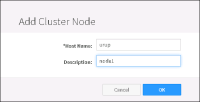
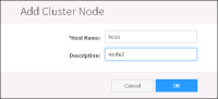
2 On Add Cluster Node, set the following properties, as shown in Figure 7‑5. A property name appearing with an asterisk (*) next to the name is a required property.
Host Name
Type the cluster node computer name.
Description
Type a description for the node.
Figure 7‑5 Adding a cluster node
Choose OK.
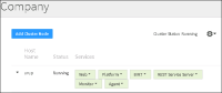
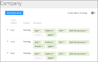
System Console displays the following information about the cluster node, as shown in Figure 7‑6:
Host Name
The machine name of the cluster node
Status
Status is either Running or Not Running
Services
The services running on the cluster node
Figure 7‑6 Viewing cluster node host name, status, and services
How to add the second cluster node to a cluster and enable the default volume
Before adding the second node, kozu, to the cluster, the system administrator performs the following tasks:
On urup, the system administrator:
Creates a folder for the shared configuration directory and shares it.
Shares the folder containing the files for the out-of-the-box (OOTB) sample volume, Default Volume.
After performing these tasks at the operating system level, the system administrator performs the following tasks in System Console:
1 On Cluster Configuration, choose Add Cluster Node, as shown in Figure 7‑6.
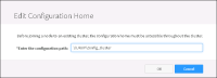
2 On Edit Configuration Home, in Enter the configuration path, type the path to the shared configuration directory, using UNC format, as shown in Figure 7‑7. UNC format supports all nodes in the cluster finding the shared configuration directory. The path you type is the path that appears as the Network Path in Properties—Sharing for the shared configuration directory. In this example, the shared configuration directory, config_cluster, is on a machine named URUP. Choose OK.
Figure 7‑7 Specifying the path of the shared configuration directory
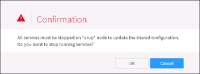
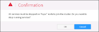
3 On Confirmation, choose OK to stop the services on the previously added cluster node, urup in this example, as shown in Figure 7‑8.
Figure 7‑8 Stopping the services on previously added cluster node
4 On Add Cluster Node, specify the machine name of the cluster node you are adding and optionally, a description, as shown in Figure 7‑9. Choose OK.
Figure 7‑9 Specifying name and description of node you are adding
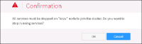
5 On Confirmation, choose OK to stop the services on the node you are adding to the cluster, as shown in Figure 7‑10.
Figure 7‑10 Stopping the services on the node you are adding to the cluster
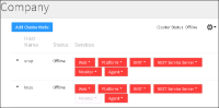
System Console adds the second node to the cluster, as shown in Figure 7‑11. By default, the Monitor service runs only on the node having the shared configuration directory.
Figure 7‑11 Viewing the second node added to the cluster
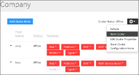
6 Choose Start Cluster from the Manage Cluster menu, as shown in Figure 7‑12. Then, choose Refresh from this menu to update the status of the services during the Start Cluster operation.
Figure 7‑12 Choosing to start the cluster
Wait until all services that are red turn green before proceeding to the next step, as shown in Figure 7‑13.
Figure 7‑13 Viewing the started services on both nodes
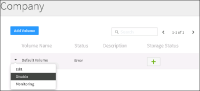
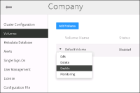
7 Choose Volumes from the side menu. Default Volume shows a status of ‘Error’. Left-click the arrowhead icon next to Default Volume and choose Disable, as shown in Figure 7‑14.
Figure 7‑14 Choosing to disable Default Volume
On Confirmation, choose OK to confirm that you want to disable the Default Volume.
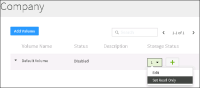
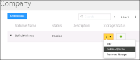
8 On Volumes, left-click the arrowhead icon in the first Storage Status box for Default Volume and choose Set Read Only, as shown in Figure 7‑15.
Figure 7‑15 Choosing set Default Volume to Read Only
On Confirmation, choose OK to confirm that you want to change the status of the volume to Read Only.
9 On Volumes, left-click the arrowhead icon in the first Storage Status box for Default Volume and choose Edit, as shown in Figure 7‑16.
Figure 7‑16 Choosing to edit Default Volume storage
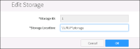
10 On Edit Storage, in Storage Location, type the path to the Default Volume storage folder, storage, using UNC format, as shown in Figure 7‑17. UNC format supports all nodes in the cluster finding this folder. The path you type is the path that appears as the Network Path in Properties—Sharing for the storage folder after sharing it. In this example, the Default Volume storage folder is on a machine named URUP. Choose OK.
Figure 7‑17 Specifying the Default Volume storage folder
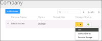
11 On Volumes, left-click the arrowhead icon in the first Storage Status box for Default Volume and choose Set Read/Write, as shown in Figure 7‑18.
Figure 7‑18 Setting Default Volume to Read/Write status
On Confirmation, choose OK to confirm that you want to change the Default Volume state to Read/Write.
12 On Volumes, left-click the arrowhead icon next to Default Volume and choose Enable, as shown in Figure 7‑19.
Figure 7‑19 Enabling Default Volume
On Confirmation, choose OK to confirm that you want to enable Default Volume.
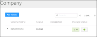
Default Volume is enabled and ready for use, as shown in Figure 7‑20.
Figure 7‑20 Viewing Enabled status of Default Volume
How to add a third or subsequent node
Before adding the third node, tupo, or any subsequent node, to the cluster, the system administrator performs the following tasks:
On tupo, the system administrator:
Turns off the firewall
Obtains the machine name and IP address
Ensures that the logon account for the Actuate iHub service on the node has administrator privileges
On both urup and tupo, the system administrator pings each machine from the other machine to ensure the machines can communicate.
After performing these tasks at the operating system level, the system administrator performs the following tasks in System Console:
1 On Cluster Configuration, choose Add Cluster Node.
2 On Add Cluster Node, specify the machine name of the cluster node you are adding and optionally, a description, as shown in Figure 7‑21. Choose OK.
Figure 7‑21 Specifying name and description of node you are adding
3 On Confirmation, choose OK to confirm that you want to stop the services on tupo, as shown in Figure 7‑22.
Figure 7‑22 Stopping services on the third node
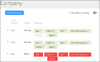
System Console adds the third node to the cluster, as shown in Figure 7‑23. By default, the Monitor service runs only on the node having the shared configuration directory.
Figure 7‑23 Viewing the second node added to the cluster
4 Left-click the arrowhead icon next to tupo and choose Start Node, as shown in Figure 7‑24. Then, choose Refresh from this Manage Cluster menu to update the status of the services during the Start Node operation. When all the services that are red turn green, the node is ready for use.
Figure 7‑24 Choosing to start the cluster
5 Choose Refresh from the Manage Clusters menu to update the status of the services during the Start Node operation, as shown in Figure 7‑25. When the services appear green, the node is ready for use, as shown in Figure 7‑26.
Figure 7‑25 Refreshing the status of services on the third node
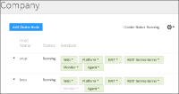
By default, the Monitor service runs only on the node containing the shared configuration directory, urup, in this example.
Figure 7‑26 Viewing the running services in the cluster
Preparing the iHub cluster environment
The system administrator performs the following tasks to support clustering:
Creates the shared configuration directory
Shares the folders that all cluster nodes access
Configures two nodes to communicate with each other
Specifies a logon account for the Actuate iHub 3.1 service on a cluster node, if necessary
This section provides examples of these tasks in the Windows environment where System Console and BIRT iHub Visualization Platform were installed as individual modules.
AC_SHARED_HOME is a variable that represents the folder that contains the shared configuration directory, to which all nodes in a cluster share access. This section makes reference to the following AC_SHARED_HOME variable settings:
In a default BIRT iHub installation on Windows, where BIRT iHub Visualization Platform was installed as an individual module to a folder named C:\Actuate3\BIRTiHubVisualization, AC_SHARED_HOME represents the following path:
In a default BIRT iHub installation on Windows, where BIRT iHub Visualization Platform was installed at the same time as System Console, to a folder named C:\Actuate3, AC_SHARED_HOME represents the following path:
C:\Actuate3\iHub3\modules\BIRTiHub\iHub\shared
In a default BIRT iHub installation on Linux, where BIRT iHub Visualization Platform was installed as an individual module to a folder named /opt/actuate, AC_SHARED_HOME represents the following path:
In a default BIRT iHub installation on Linux, where BIRT iHub Visualization Platform was installed at the same time as System Console, to a folder named /opt/actuate, AC_SHARED_HOME represents the following path:
/opt/actuate/iHub3/modules/BIRTiHub/iHub/shared
Creating the shared configuration directory
The system administrator creates the folder for the shared configuration directory on urup before adding the second node to the cluster.
How to create the shared configuration directory
On urup, in AC_SHARED_HOME, create a new folder for the cluster to use as the shared configuration directory. For example, create a folder named config_cluster.
Sharing the folders that all cluster nodes access
In a BIRT iHub installation, cluster nodes must have read‑write access to the following folders in AC_SHARED_HOME on urup:
config_cluster
The shared configuration directory. System Console populates this folder when the system administrator adds the second node to the cluster.
storage
Contains the data files for the sample volume, Default Volume.
The system administrator shares these folders before adding the second node to the cluster.
Note that you must share the folder containing the data files for any volume you add to the cluster. For more information, see Adding a volume.
The following instructions provide a basic example of the operations required to configure network sharing. It is the responsibility of the system administrator performing this task to make sure that all settings conform to the security policies in force for the environment.
How to share the \config_cluster and \storage folders
To give a cluster node read-write access to these resources on urup perform the following tasks:
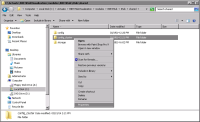
1 Using Windows Explorer on urup, right‑click the config_cluster folder, and choose Properties, as shown in Figure 7‑1.
Figure 7‑1 Choosing Properties
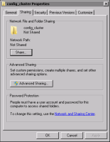
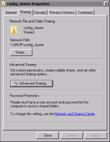
2 On config_cluster Properties, choose Sharing, as shown in Figure 7‑2. On Sharing, choose Advanced Sharing.
Figure 7‑2 Choosing Advanced Sharing
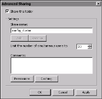
3 On Advanced Sharing, select Share this folder, as shown in Figure 7‑3.
Figure 7‑3 Selecting Share this folder
On Advanced Sharing, choose Permissions.
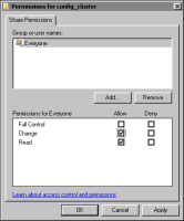
4 On Permissions for config_cluster, in Share Permissions, select Allow for Change and Read, as shown in Figure 7‑4.
Choose OK.
Figure 7‑4 Selecting Change and Read permission
On Advanced Sharing, choose OK.
On config_cluster Properties, take note of the Network Path, as shown in Figure 7‑5. You specify this path when adding the node to the cluster in System Console. Choose Close.
Figure 7‑5 Taking note of the Network Path
5 Repeat steps 1 through 4 for the storage folder that contains the sample volume files. Make sure that all settings conform to the security policies in force for the environment.
In step 4, take note of the Network Path appearing on storage Properties—Sharing. You specify this path when enabling Default Volume in System Console after adding the second node to the cluster.
Close Windows Explorer.
Configuring two nodes to communicate with each other
Before adding a node to a cluster, perform the following tasks to support communication between the node containing the shared configuration directory, for example node1, and the node you are going to add to the cluster, for example node2.
Turn off a Windows firewall.
Obtain the machine name and IP address of each machine.
Test the network connection between the two machines.
How to turn off a Windows firewall
Perform the following steps on both node1 and node2:
1 Choose Start➛Control Panel➛System and Security➛Windows Firewall.
2 On Windows Firewall, choose Turn Windows Firewall on or off. Make sure that the firewall settings conform to the security policies in force for the environment.
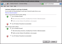
3 On Customize Settings, in Home or work (private) network location settings, choose Turn off Windows Firewall, as shown in Figure 7‑6.
Figure 7‑6 Turning off the home or work network location firewall
Choose OK.
How to display a computer’s IP address
To obtain the host names of node1 and the computer on which you will install the cluster node, perform the following tasks on node1 and node2:
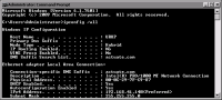
Press Enter. The host name appears, as shown in Figure 7‑7. In this example, the host name for node1 is urup.
Figure 7‑7 Displaying the host name
3 Write the host names and IP addresses of the computers to be clustered, as shown in Table 7‑1.
Table 7‑1 Host names and IP addresses of computers to be clustered
iHub
Host name
IP address
node1
urup
192.168.41.140
node2
kozu
192.168.41.138
How to test the connection between computers
Perform the following steps on both computers:
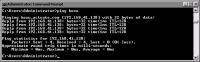
1 In Command Prompt, type the ping command followed by the IP address or host name of the other computer. For example, type the following command to ping a computer named kozu:
ping kozu
Press Enter.
If your computer reaches the other computer, Command Prompt displays a series of replies, as shown in Figure 7‑8.
Figure 7‑8 Receiving a reply to a ping command
2 Close Command Prompt.
Specifying a logon account for the Actuate iHub 3.1 service on a cluster node
Before adding the node to the cluster, the system administrator checks the Actuate iHub 3.1 Service Log On property for whether it specifies an account having administrator privileges. If the Log On property does not specify an account having administrator privileges, the system administrator performs the following tasks on the node:
Stops the Actuate iHub 3.1 service
Specifies a logon account for the Actuate iHub 3.1 service that has administrator privileges
Restarts the Actuate iHub 3.1 service
How to check the Actuate iHub 3.1 Service Log On property
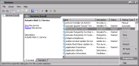
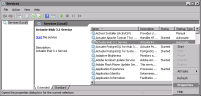
1 Choose Start➛Control Panel➛System and Security➛Administrative Tools➛Services. On Services, right-click Actuate iHub 3.1 Service, and choose Properties, as shown in Figure 7‑9.
Figure 7‑9 Choosing Actuate iHub 3.1 Service properties
2 On Actuate iHub 3.1 Service Properties, choose Log on. If This account already specifies an account having administrator privileges, as shown in the example in Figure 7‑10, you do not need to specify a logon account for the Actuate iHub 3.1 service. Choose Cancel on Actuate iHub 3.1 Service Properties, and close Services. Otherwise, perform the tasks described in How to specify a logon account for the Actuate iHub 3.1 service.
Figure 7‑10 Checking the Log On property
How to specify a logon account for the Actuate iHub 3.1 service
1 Choose Start➛Control Panel➛System and Security➛Administrative Tools➛Services. On Services, select Actuate iHub 3.1 Service. Then, choose Stop the service, as shown in Figure 7‑11.
Figure 7‑11 Stopping the Actuate iHub 3.1 service
2 On Services, right-click Actuate iHub 3.1 Service, and choose Properties, as shown in Figure 7‑12.
Figure 7‑12 Choosing Properties for the Actuate iHub 3.1 service
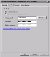
3 On Actuate iHub 3.1 Service Properties, perform the following tasks:
1 Choose Log On.
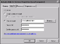
2 In Log On, select This account, and specify an account that has administrator privileges, such as <machine name>\administrator.
3 In Password and Confirm password, type the password for the account.
4 Choose Apply. Figure 7‑13 shows Actuate iHub 3.1 Service Properties—Log On for a machine named kozu.
Figure 7‑13 Specifying an account with administrator privileges
Choose OK.
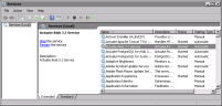
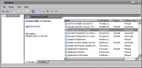
4 On Services, select Actuate iHub 3.1 Service, and choose Start the service, as shown in Figure 7‑14.
Figure 7‑14 Starting the Actuate iHub 3.1 service
Understanding Cluster Configuration
In Cluster Configuration, the system administrator adds a cluster node to the cluster. Additionally, Cluster Configuration supports management tasks such as starting, stopping, and editing the properties of the following:
The entire cluster
An individual cluster node
A service running on a cluster node
Performing management tasks for the entire cluster
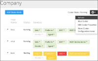
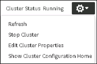
The system administrator chooses the cog-shaped icon to access the Manage Cluster menu, as shown in Figure 7‑15.
Figure 7‑15 Accessing the Manage Cluster menu
The Manage Cluster menu consists of the following options:
Refresh
Refreshes the status of the services running on all cluster nodes.
Stop or Start Cluster
Stops or Starts all nodes in the cluster. If the cluster is running, or online, Stop Cluster displays in the Manage Cluster menu. If the Cluster is stopped, or offline, Start Cluster displays in the Manage Cluster menu.
Edit Cluster Properties
Displays Edit Cluster Properties. The system administrator can change any of the following cluster properties. Choose Stop Cluster to stop the cluster before changing Cluster URL.
Name
Description
Cluster URL
Password
After making any cluster property changes choose OK. If you changed the Cluster URL, choose Start Cluster to start the cluster after choosing OK.
Show Cluster Configuration Home
Displays the location of the shared configuration folder that the AC_CONFIG_HOME element specifies in the acpmdconfig.xml file on the cluster node, in UNC format. For example, the following line specifies the path to the shared configuration folder used in How to add the second cluster node to a cluster and enable the default volume:
\\urup\config_cluster
urup is the name of the machine containing the shared configuration folder.
In a default BIRT iHub installation on Windows, performed using the installer, in which the install folder is C:\Actuate3, the path AC_CONFIG_HOME specifies is:
Performing management tasks for an individual cluster node
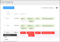
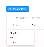
The system administrator chooses the arrowhead icon next to a cluster node name to access the cluster node menu, as shown in Figure 7‑16.
Figure 7‑16 Accessing the cluster node menu
The following list describes the options on the cluster node menu:
Stop or start node
Stops or Starts the cluster node. If the cluster node is running, or online, Stop Node displays in the cluster node menu. If the cluster node is stopped, or offline, Start Node displays in the cluster node menu.
Edit
Displays Edit Cluster Node. The system administrator can change either of the following properties:
Host Name
Description
Delete
Deletes the node from the cluster.
Performing management tasks for a service running on a cluster node
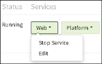
The system administrator chooses the arrowhead icon next to a service name to access the service menu. For example, Figure 7‑17 shows the menu for the Web service.
Figure 7‑17 Accessing a service menu
The following list describes the options on any service menu except the BIRT menu. For more information about the BIRT service, see About the BIRT service.
Stop or Start Service
Stops or Starts the service. If the service is running, the color of the icon for the service is green, and Stop Service displays in the service menu. If the service is stopped, the color of the icon for the service is red, and Start Service displays in the service menu.
Edit
Displays Edit <service name>. For example, when the system administrator chooses to edit the Web service, System Console displays Edit Web.
For each service, Edit <service name> displays the Startup Mode, Process Name, and Java Arguments properties, as shown in Table 7‑1. The system administrator can change the Startup Mode and the Java Arguments properties. A property name appearing with an asterisk (*) next to the name is a required property.
If you modify the Java heap size argument for a service, do not specify a size that exceeds the amount of RAM on the node. On some Linux platforms, the LMServer process may encounter an error if the Java heap size you specify exceeds the amount of RAM available on the node.
Choosing the arrowhead icon next to BIRT displays a menu containing one option, Edit.
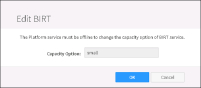
When the system administrator chooses Edit on the menu for BIRT, System Console displays Edit BIRT, as shown in Figure 7‑18.
Figure 7‑18 Editing the BIRT service
Changing the Capacity Option changes the server configuration template that configures this cluster node. AC_CONFIG_HOME\acserverconfig.xml contains the server configuration templates. The names of the default server configuration templates in acserverconfig.xml are small, medium, large, and disable. Stop the Platform service before changing the name for Capacity Option in Edit BIRT.